Sampling systems are the reason the lab number can be trusted — or quietly wrong for months. Between the process tap and the analyzer lives a chain of small hardware decisions, and every one of them filters, delays or distorts the sample before the sensor ever sees it. The good news: the chain is finite, the rules at each link are published, and most failures trace to three mistakes — a badly placed take-off, an unfiltered leg, and a sample line long enough to lag the process by minutes. Walk the chain once and the RFQ writes itself.
Key takeaways
- The take-off comes first and decides everything downstream: sample from a flowing, representative zone — probe to pipe center, away from dead legs and low points.
- Double block and bleed at the tap lets the probe and its hardware be serviced without opening the process.
- Transport lag is line volume divided by flow rate — long small-bore lines add minutes; fast loops and short runs are the fix.
- The conditioning chain is filter, pressure reduction, flow control — each link with its own component discipline.
- The final needle at the analyzer sets the actual sample flow; the loop-level decisions set whether that flow is fresh.
The take-off point
Analysis is only as honest as the point the sample leaves the process. The placement guidance is consistent across the sampling references: tap where the stream is moving and representative — probe inserted toward the pipe center — and away from the places where the process stops being itself: dead legs, stagnant lines, the bottoms of horizontal runs where liquid pools, and the neighborhood of tees where mixing is chaos. Gas taps on horizontal pipe go on top, where droplets and particulate are least likely to ride into the line; ten diameters of straight run upstream is the published comfort zone. A probe that samples the wall boundary layer reports the wall, not the stream — and no downstream hardware fixes a sample that was wrong at birth.
The probe and block
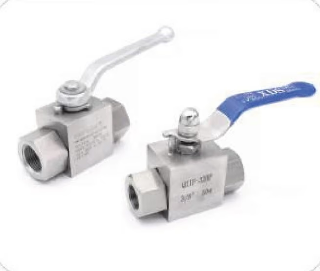
Between the process and everything you own stands the isolation question, and the answer is the double block and bleed pattern from double block and bleed valves explained: two barriers in line, a bleed between them, so the probe and its downstream string can be vented and serviced while the process runs on. Sampling suppliers build probe valves on exactly this pattern — primary and secondary block with a bleed — because the alternative, a single gate you trust with your zero, is how plants end up venting process fluid into the analyzer shelter. Pair the isolation with the manifold discipline of instrument manifold styles and the tap is both safe and serviceable.
Fast loop vs slow loop
Distance is the enemy of freshness, and the arithmetic is unforgiving: transport lag is the sample-line volume divided by the flow rate — the references publish it exactly that way, with a worked figure of roughly 110 seconds through 100 meters of quarter-inch tubing at a liter a minute. The industry answer is the fast loop: a high-flow bypass that carries fresh sample most of the way to the analyzer and returns the excess to process, with only a thin bleed through the conditioning chain and sensor. Fast-loop flow is designed to be much faster than the analyzer leg, so what the sensor finally sees arrived seconds ago, not minutes. The budget figures vary by reference — a one-minute response is quoted as the common industry standard, 60 seconds as generally satisfactory, gas lines to about 100 meters workable single-run, fast loops mandatory past roughly 50 meters — so state the lag budget your control loop needs on the RFQ rather than inheriting someone else’s.
Conditioning: filter, regulator, orifice
Conditioning turns raw tap fluid into something the sensor can read, link by link. The filter stands first, because everything downstream is small-passage hardware — the inline filters for instrument lines post carries the rating logic. Pressure reduction follows, dropping process pressure toward analyzer levels, with the phase-change caveat that liquid samples flash as pressure falls — keep liquids high-pressure until the design says otherwise, per the vaporization references. Flow control comes last before the sensor: a fixed restrictor for the set-and-forget legs, a metering orifice where the flow is the spec — the orifice union fittings post — or a needle where an operator tunes it by hand. Where the process pulses, the gauge snubber logic carries over directly: damp the ripple before it becomes noise at the sensor.
The final valve: needle to analyzer
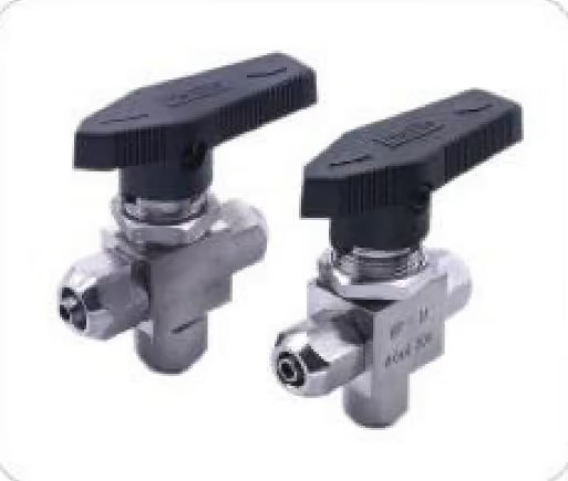
At the analyzer inlet, a needle valve sets the actual sample flow — the references show the pattern of a rotameter or flowmeter with a needle valve for manual adjustment as the standard terminal arrangement. This is fine metering at small scale, the duty a needle was built for, and the selection logic is the same one from the needle valves range: fine thread, small orifice, repeatable setting. Custom probe stations and mixed-standard transitions are the custom fittings territory.
RFQ lines
take-off— pipe size, insertion, orientation: the placement facts that decide representativeness.distance to analyzer— meters and the lag budget, so fast-loop decisions are made at quote time.fluid and phase— gas or liquid, pressure and temperature at the tap, and where flashing is allowed.conditioning chain— filter grade, regulator range, restrictor or needle, and where each sits.- One line list, one quote: the whole chain prices together.
FAQ
How long can a sample line be?
Arithmetic, not dogma: lag equals line volume over flow rate, so the length limit is set by the lag budget. The references put workable single gas lines near 100 meters, call 60 seconds a generally satisfactory response, and push fast loops mandatory past roughly 50 meters — with safety interlocks wanting far less. State the seconds your control loop can tolerate, and the diameter, flow and loop architecture follow.
What is a fast loop for?
Freshness. A fast loop moves sample quickly most of the way to the analyzer and returns the excess to process, so the thin stream that actually reaches the sensor left the tap seconds ago instead of minutes. It is the standard answer whenever the take-off sits far from the analyzer, and it beats the alternatives of pretending the lag is not there or relocating the shelter by feel.
Where does the filter go in a sampling system?
First, before everything with small passages — regulators, restrictors, sensors. Debris that would scar a regulator seat or clog a fixed orifice is stopped at the barrier, and the differential pressure across the element becomes the service meter. Clean it early in the chain and the rest of the conditioning train stays alive.
Why double block and bleed at the sample tap?
Because the tap is the one joint that must open while the process runs. Two barriers in line and a bleed between them let the probe and downstream string be vented and serviced without depressurizing the process or venting fluid into the shelter. Single-valve trust is how sample systems become exposure stories; DB&B is the published pattern for exactly this duty.
What controls the actual flow to the analyzer?
The terminal needle, read against a rotameter or flowmeter — the standard final arrangement. The loop-level hardware decides freshness and cleanliness; the needle at the analyzer decides the flow rate the sensor actually sees. Specify both: the chain that delivers a clean, fresh sample, and the fine valve that meters it.