Instrument impulse lines are the small-bore tubes that carry process pressure from the tap on the pipe or vessel to the transmitter, gauge or switch that reads it. They look like plumbing afterthoughts and they are not: a trapped gas bubble in a liquid line, a frozen condensate pocket in a winter header, or a sagging undrained low point turns a good transmitter into a liar. Here is what impulse lines are, how to route them, and what belongs at each end.
Key takeaways
- An impulse line holds a static column of fluid whose only job is to transmit pressure faithfully — any real flow in it creates error, so short, direct, same-bore runs win.
- Route with a continuous slope so the unwanted phase escapes: liquid service vents gas back toward the process or a high vent; gas service drains condensate back toward the process or a low drain — slope values are project- and maker-specific, not universal constants.
- Keep the two legs of a differential-pressure pair as alike as possible — similar length, similar temperature exposure — or the imbalance shows up as zero error.
- Freeze protection is a system decision — insulation alone may not stop a freezing line; heat tracing, enclosures and routing are evaluated together. The isolation end of the line — root valves and manifolds — is where instrumentation fittings do their real work.
What the line is and is not
The impulse line is not a process pipe. A process pipe transports fluid; an impulse line holds a still column of process fluid — or of a sealing fluid — whose pressure must equal the tap pressure at every moment. That framing explains every routing rule. Anything that disturbs the static column disturbs the measurement: a trapped gas bubble in a liquid line compresses and adds lag; a condensate pocket in a gas line adds a liquid head; a long skinny run adds response delay; a leak adds error and hazard. Small-bore tubing — commonly around 1/2 inch OD in industrial practice — is the usual choice for instrument runs because it minimizes volume and responds fast; pipe enters for longer, hotter or more demanding runs where the project spec calls for it. Tube sizing itself is its own discipline: the ferrule seals on actual OD, which is why the tube-versus-pipe distinction matters at every joint.
Routing: slope, drain, and no traps
The governing principle is phase management. For liquid service, run the line so any liberated gas can vent back to the process or to a high-point vent; for gas service, run it so condensate drains back to the process or to a low-point drain. A practical arrangement puts the instrument below the tap for liquids and above it for gases, subject to the process and instrument design. Keep a continuous one-direction slope on nominally horizontal runs — maker and project guidance variously specifies gradients from about one-in-ten down to a few percent, and the right number comes from the instrument maker or project standard, not from a universal constant. Whatever the gradient, avoid intermediate high and low points: each crest traps gas in a liquid line, each sag traps liquid in a gas line. Where a pocket is unavoidable, add a vent or drain and account for the resulting head. And keep both legs of a differential-pressure pair matched in length and temperature exposure — an unmatched pair is a standing zero error.
Some services deliberately keep liquid in the line. Steam measurement commonly maintains condensate-filled legs with seal pots so the transmitter sees a stable, known water head rather than live steam. The point is not “keep lines dry”; it is “control what is in the line.”
Material, freezing, and the ends of the line
Material selection follows the process fluid and the design conditions, not habit: 316 tubing for chloride-bearing service, the project-specified alloy for aggressive media, and everything — tube, fittings, valves, manifold — rated together for pressure and temperature. The sizing and ordering side of that is covered in pipe vs tube, because an impulse line quoted as pipe when the panel expects tube arrives wrong.
Freezing is the classic impulse-line failure: condensate freezes, the line plugs, the reading freezes at a plausible value, and ice splits components. Treat freeze protection as a system — insulation, heat tracing, heated enclosures and routing evaluated together, since insulation alone only slows the freeze. If the process fluid itself can freeze or solidify, seal pots and filling fluids isolate the instrument from it.
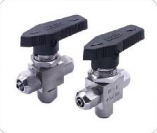
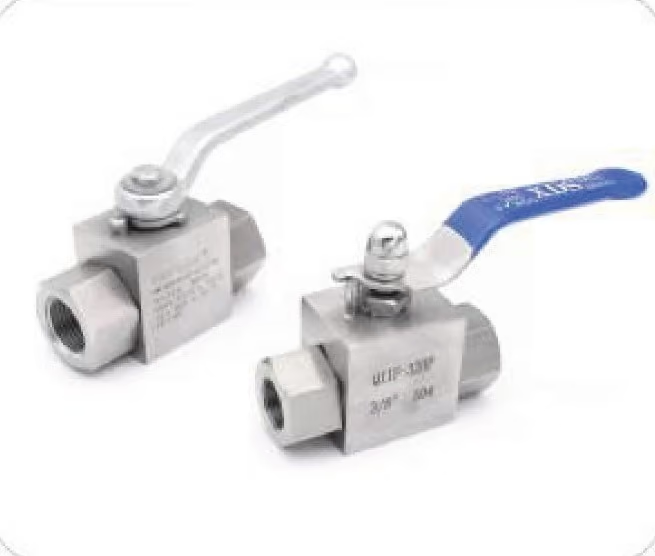
At each end of the line, purpose-built hardware does the isolation. The root valve — a gauge root valve for a gauge — sits at the tap as primary isolation. At a transmitter, an instrument manifold takes over the instrument side: blocks, equalize and vent or drain in one body, which is the 3-valve manifold and 5-valve manifold territory, and the manifold does not replace the process-side root valve. The hookup style this enables across oil and gas skids is mapped on the oil & gas instrumentation page. Quote the run as one bill of material — tube, fittings, root valve, manifold — and everything arrives matched and documented together.
Send the hookup sketch or the tap-to-instrument run list — tube OD and wall, fitting styles, root valve and manifold configuration, service conditions — and we quote the line as one package. Request a factory quote.
FAQ
What is an impulse line in instrumentation? The small-bore tube or pipe that connects a process pressure tap to a transmitter, gauge or switch. It holds a static column of fluid whose pressure must equal the tap pressure, so anything that disturbs the column — trapped gas, trapped liquid, leaks, delays — disturbs the measurement.
What slope should an impulse line have? Enough to keep the unwanted phase moving: continuous one-direction slope on nominally horizontal runs, toward a vent for liquid service or a drain for gas service. Gradient values are project- and manufacturer-specific — commonly in the one-in-ten to a-few-percent range — so take the number from the instrument maker or project standard.
How do you keep impulse lines from freezing? As a system, not a single product: evaluate insulation, heat tracing, heated enclosures and routing together. Insulation alone may only slow freezing. Where the process fluid can freeze, seal pots or filling fluids isolate the instrument from the process fluid itself.
Tube or pipe for impulse lines? Small-bore tube is the usual choice for instrument runs — small volume, fast response, ferrule-sealed joints; pipe appears on longer, hotter or project-specified runs. Whichever the spec says, state it explicitly, because tube sizes by actual OD and pipe by NPS, and they do not interchange.
What valves belong on an impulse line? A root valve at the tap for primary process isolation — a gauge root valve for gauges — and, at a transmitter, an instrument manifold providing block, equalize and vent or drain. The manifold supports instrument work; it does not replace the process-side root valve.
Do instrument tubing and compression joints need a hydrotest? Not automatically. ASME B31.3 para. 345 requires each piping system to be proven tight before initial operation, with hydrostatic testing per para. 345.4 as the norm — but two provisions carry instrument connections. For Category D fluid service, para. 345.7 lets the owner choose an initial-service leak test in place of the hydro. And the code states outright that threaded joints, tubing joints, or a combination used to connect instruments to previously leak-tested piping need not themselves be leak tested under para. 345. That exception is narrow: it covers the instrument connection off an already-tested line, not a tubing run that is itself process piping. Where the tubing carries hazardous media or falls under a jurisdiction or contract that demands it, it gets tested with the system — which is also where an under-torqued compression joint shows itself, as a leak at test pressure rather than a leak in service.